Why is the reducer shell electrified
2021年1月8日When the reducer cannot be started, the motor cannot be forcibly started many times, which will cause damage to the motor. It should be analyzed in detail based on the actual situation and symptoms, and start after finding out the reason why the reducer cannot be started. The purpose of this is to prevent the expansion of electric faults. What are the reasons for the electrification of the reducer housing? Why is the reducer housing live? Especially when the reducer makes abnormal noise or overheating, the power supply should be disconnected in time when the temperature is too high to ensure that the electric motor is not damaged. To protect the motor from these small problems, solving these small problems can avoid the expansion of electric failures, and can extend the service life of the electric.
When the reducer cannot move, we should start to find the reason from the following aspects:
1. Check whether the power of the reducer is connected;
2. The fuse is blown;
3. The stator or rotor winding is open;
4. The stator group is grounded;
5. Short circuit between stator windings;
6. Wiring error of stator group;
7. The overloaded transmission machinery is crushed;
8. The rotor copper bars are loose;
9. Whether the lubricating grease in the reducer bearing is used up, the reducer has been added with lubricating grease before leaving the factory. It runs for 20000 hours under normal conditions without changing the lubricating grease, but when operating under special environmental conditions, such as high temperature, long time The oil change frequency is 10000-15000 hours during operation. Therefore, you should pay attention to the frequency of oil replacement when using the reducer. There may also be the expansion of the rotating shaft due to heat, which prevents the rotation in the bearing.
10. Wiring error or damage to control equipment;
11. The overcurrent breaker is adjusted too small;
12. The oil cup of the old walking switch is short of oil;
13. The rotor resistance of the wound rotor motor is improperly equipped.
The housing of the reducer in normal operation is not allowed to be charged. In order to prevent the housing of the motor from being charged, the common reasons that cause the housing of the motor to be charged are summarized as follows.
1. The power line and the ground line are wrong;
2. Leakage caused by damage to the stator winding insulation. The reasons are: the three-phase asynchronous motor has been used for too long and the winding insulation is aging; or foreign matter enters the motor and damages the winding insulation; or the motor is overloaded for a long time and the winding is burned out; or the power supply voltage exceeds the rated motor Voltage causes insulation breakdown of stator windings, etc. These may make the metal shell of the motor live. In addition, if the environment around the motor is humid; or the motor is under rain and snow, water droplets enter the motor; or due to the erosion of harmful gases. These will reduce the insulation performance of the three-phase fixed winding (decrease the insulation resistance) and make the metal shell of the motor live.
3. The motor windings are in love with the tide, and the insulation aging reduces the insulation performance;
4. The lead wire and the junction box touch the shell;
5. Local winding insulation damage causes the wire to touch the shell;
6. The connection to the first line fails;
7. The wiring board is damaged or the surface is oily;
8. The iron core is loose and punctures the wire.
It is an admitted fact that the gear mechanism helps us to have energy to a great extent. As we all know that it is this setup that generates force and transfers it from one source to another through some device adjoined with each other. We owe to the Romans for the invention of it. Now with the aid of it we access modern power technology. It seems there is no such machine sans this basic device at the present moment.
Gears helps us through a mechanism of rotation between two axes to generate power. Thus they, with the help of rotation following a mechanical theory related to physics transfers speed into power. They may be of two sizes, one small and the other large, adjoining each other with the help of teeth. The teeth are interlocked and cause rotation.There are various types associated with various machines to help us. The ones that are used in the watches and clocks are called spur gears that help the machine to function accordingly. If they weren’t present, our watch would not work.
Again vehicles run too with the help of gears. The ones used in this sector are Helical and help to ply a vehicle perfectly. Without their aid, it is not possible for the vehicle to move an inch.The teeth, we know, play the pivotal part. If the teeth of the two pinions differ in number there may emerge major problem. The ratio of the device must comply wit norms; otherwise according to the rule of physics, problem is sure to ensue. The theory that works here is that the force input must have equilibrium with the force that is static. In this way the friction caused is adjusted with the ratio.
If between two gears one is heavier and the other lighter it is noted that the weight becomes the great factor to cause friction. If the weight seems too heavy rotation may be hampered causing inconvenience to move the machine with which they are attached.
Different gears have different teeth. The teeth are in a twisted form or in a straight form. It is the action of a helical one to radiate motion between two shafts. Whereas the bevel kind has teeth based on conical surface. The shafts are never parallel and intersected sharply in an angle.We cannot but explain another type in this context. It is the hypoid one that is used in moving a vehicle. It is attached to the part called differential. The action of this gear is connected with the axle that is at the extreme end of a vehicle. With the rotation of it the vehicle moves and the mechanism is intact. Again, there is another called the worm most likely to resemble a screw that is used to transfer motion to two different shafts.
Planetary reducer is an industrial product with a wide range of applications. Its performance is comparable to other military reducers, but its price is the same as that of ordinary industrial products. Therefore, it is very popular in many industrial fields. In this article, some basic concepts of this reducer will be introduced to help people quickly understand the general concepts. The first is the series about it. It refers to the series of planetary wheels. Sometimes, because a set of planetary gears cannot meet a relatively large transmission ratio, one or two sets of gears need to be added to meet the requirements of the transmission ratio. As the gears increase, the length of the reducer will increase accordingly and the efficiency will decrease to some extent. The next concept is about rebound. The so-called gap means a small angular displacement. The unit of this recoil is "minute", which means one-sixtieth of a degree. The rear gap is another name.
Since people have some ideas about this type of reducer, they now begin to talk about its functions and characteristics. As far as we know, the main transmission structure of planetary reducer includes planetary gear, sun gear and outer ring. Compared with other reducers, planetary reducers have the following characteristics: high rigidity, high precision, high transmission efficiency, high torque ratio and lifetime maintenance. Based on these characteristics, most planetary reducers are mounted on stepping motors and actuation motors.
Their main function is to reduce the speed and increase the torque. They also play an important role in matching inertia. Moreover, in addition to the above advantages, it also has other unique features. It is small in size, light in weight, high in load capacity, long in service life, and very stable in operation without much noise. Because of its different characteristics, it is indeed very popular in different fields, such as engineering factories, metallurgy, mining, petrochemical industry, construction machinery, light industry, automobiles, ships and weapons. The temperature range of the reducer is -25 to 100 degrees Celsius. At the same time, the working temperature can be changed by replacing the grease. All in all, the reducer is very popular in the industry.
A worm gear reducer is a right angle gear set that gives you the greatest possible amount of speed reduced while being considerably smaller in volume than other types of gear arrangements.The worm gear arrangement is also known as a worm drive. It is composed of a worm that is combined with a worm gear (WG). Now, a worm is the spirally threaded shaft (similar to a screw) of a WG set. The WG, or worm wheel, is similar to a spur gear but considerably smaller in volume. A WG reducer, like other gear sets or arrangements, can decrease rotational speed or allow the transmission of higher torque. This is usually the perfect choice if you need to reduce motor speed by a large amount in a single step. The normal reduction range for a single worm gear is 5:1 up to 100:1. The WG ratio is based on the number of threads on the worm and the gear’s teeth. The ratio is higher if the number of threads on the worm is less.
There are different types of worm gears:
· Non-throated - both the worm and the worm gear have no throat or grooves carved around their circumferences.
· Single-throated - one element which is usually the driven gear is throated or has grooves. A single moving point on the worm drive is where tooth contact takes place. This line contact allows for higher loads without excessive wear.
· Double Throated - also known as a cone or hourglass. Both the worm and the driven gear have concave teeth. This type of gear set can support the largest amount of weight.
Characteristics:
· For maximum mating, worm gears are helically cut
· Converts high speed inputs to low speed and high torque outputs in one simple step
· Pure sliding motion occurs
· Allows for maximum speed reduction
· Excellent for precise movement of load
· Not usually bidirectional
· Normally operates at 900F over ambient
· Has low energy-conversion efficiency
Worm gear reducers are used in a variety of machines. Some of the most usual machines that uses this type of gear set are automotive parts, rolling mills, presses, rudders and conveying engineering. A lot of elevators use WG’s as well because of its small size and non-eversibility. Small electric motors have a high speed and low torque. Using a WG reducer allows them to have more uses or applications.
With the development of national infrastructure, China’s reducer industry has developed rapidly. According to statistics from the branch, the reducer industry produced 450,000 reducers last year, with sales of 2 billion yuan. Export sales are about 100 million US dollars. Some experts predict that during the "Eleventh Five-Year Plan" period, the total economic growth of the reducer industry will reach double digits due to the country’s overall economic development.
The reducer can be widely used in various fields such as national economy and national defense. The product has developed from single cycloid pinwheel reducer to five categories. There are cycloidal pinwheel reducers, continuously variable transmissions, gear reducers, worm reducers and electric pulleys. According to preliminary statistics, the main industries that reducers are applied to are: electrical machinery, metallurgical machinery, environmental protection machinery, electronic appliances, road construction machinery, chemical machinery, food machinery, light industry machinery, mining machinery, transportation machinery, construction machinery, and construction. Material machinery, cement machinery, rubber machinery, hydraulic machinery and petroleum machinery, etc.
Due to the proactive fiscal policy adopted by the country, domestic demand has been stimulated, investment in fixed assets has been increased, and various industries have developed rapidly. In particular, investment in infrastructure has promoted the development of metallurgy, electricity, construction machinery, building materials and energy. Therefore, the demand for reducers is also increasing. It is foreseeable that during the "Eleventh Five-Year Plan" period, with the country’s attention to the machinery manufacturing industry, the acceleration of the development of large equipment and the construction of competition venues, the future of the reducer industry will be more prosperous.
The entire industry will maintain a rapid development trend, especially the gear reducer industry. The growth of gear reducers will be greatly improved, which is closely related to the wide application of these products in imported equipment. Therefore, experts suggest that companies should seize this once-in-a-lifetime opportunity to develop and manufacture gear reducers, especially large and hard surface reducers, to meet market demand.
Worm gears are used for reducing speeds and increasing torque. They are quite compact and can achieve very high speed ratios, often 60:1 or higher. Unfortunately, due to the way they operate, they produce a lot of heat and require special lubrication.
Worm gears and worms contact each other through sliding rather than rolling. This increases friction and thus the operating temperature. Worm gears may operate at close to twice the temperature of other similar gear configurations such as spur gears.
Due to the sliding motion, the worm slowly rubs off the lubricant film while engaging with the worm wheel. The worm surface picks up more lubricant after disengaging, but it is difficult to ensure that it will have a lubricant film that is thick enough to last through the load zone. As a result, worm drives require high viscosity lubricants (due to the high operating temperatures) and have good lubricity to overcome the high-load metal-to-metal contact.
There are four types of lubricants that are commonly used with worm gears: compounded mineral oils, extreme pressure (EP) mineral oils, polyalphaolefin (PAO) lubricants, and polyalkylene glycols (PAG). Compounded, mineral-based oils have natural or synthetic fatty additives that provide good lubricity and better protection against sliding wear. These oils are made from a mineral basestock, containing rust and oxidation inhibitors, and blended with acidless tallow and fatty additives.
Mineral-based, extreme pressure gear oils are often used when no brass components are present. Brass components may react with the sulfur-phosphorous additives found in these oils, although the latest EP oils utilize non-active sulfur to reduce possible corrosion. EP oils are often used for steel gears and when shock loading occurs. PAO gear lubricants have good lubricity properties to help prevent sliding wear. The additives should be checked to make sure that the oil is compatible with the gear material(s).
PAG lubricants are rather new but are becoming more common. They have excellent lubricity, a very high viscosity and are a great choice for low or high temperature operation. Please note that they are not compatible with some mineral oils, seals, and paints.
To have an understanding about the working and functioning of a gear speed reducer, you should be aware of the basic principles of mechanical engineering. First, you should understand that gears are usually round in shape, though at times cylindrical gears are also used for transmission of mechanical power. Gears come with teeth on the peripheries that interact with each other when you want to change speed, direction or torque. The housing containing the gears is called a gear box. Selection of gears enables you to decrease the speed with a resultant increase of torque. When an operator wouldn’t like the machine to run at high-speed, they include a gear reducer, comprising of a set or gears, in between the motor and the machine in operation to achieve reduction of speed and hence the power that the machine is transmitting.
An important feature of a gear speed reducer being used with other machines is its capacity to resist high shocks and withstand very heavy pressure at the time of start or when being stopped. Another desirable feature of reducers is that they should operate silently or produce minimum noise or chatter. Gear reducers are frequently used in association with industrial motors and other machines used in printing, packaging, mining and metal working industries. Other industries employing gear reducers include agriculture, horticulture, marine and many more. Since gear reducers are most often used in industrial machines, companies using such machines like to ensure that their investment keeps working without any problem or breakdown at any time. Breaking down of any production machinery results to reduced production and the inability of the manufacturer to make timely deliveries affects its reputation and profits adversely.
There are many companies manufacturing gear reducers in different designs of varying capacities.Gear reducers are required for repairing of machines and for their optimum operations. Since the likelihood of any of the components, responsible for keeping the motors running, getting broken down in operation can’t be ruled out altogether, manufacturers necessarily need the services of repair companies which can attend to various jobs at very short notices. Even a gear speed reducer may need repairs or replacement due to continuous fluctuations on motor caused by ever-changing low and high speeds. Other likely reasons that lead to repairs or the replacement of gear reducers are the lack of lubrication or inadequate maintenance.
What are the tips for using geared motors
2020年12月12日1. After the geared motor has been running for 200 to 300 hours,the oil
should be changed for the first time, and the oil quality should be checked regularly in the future use. The oil mixed with impurities or deteriorated should be replaced in time. Under normal circumstances, for long-term continuous working geared motors, the new oil should be replaced after 5000 hours of operation or once a year. For geared motors that have been out of service for a long time, they should also be replaced with new oil before restarting. Mixed use, oils of the same grade but different viscosity are allowed to be mixed.
2. When changing the oil, wait for the geared motor to cool down and there is no danger of burning, but it should still be kept warm, because after complete cooling, the viscosity of the oil increases and it is difficult to drain the oil. Note: Cut off the power supply of the transmission device to prevent accidental power-on!
3. During work, when the oil temperature rises above 80°C or the oil pool temperature exceeds 100°C and abnormal noise is found, stop using it. Check the cause, remove the fault, and replace the lubricating oil before continuing to run.
4. The user should use and maintain the rules and regulations of the gear reduction motor reasonably, and carefully record the operation of the gear reduction motor and the problems found during the inspection. The above regulations should be strictly implemented.
Inspection and maintenance:
Gear motor transmission lubricant
Grease selection When selecting the grease according to the bearing load of the gear reduction motor, the grease with a small penetration degree should be selected for heavy loads. When working under high pressure, in addition to low penetration, it also has higher oil film strength and extreme pressure performance. When selecting grease based on environmental conditions, calcium-based grease is not easily soluble in water and is suitable for dry and low-water environments. When selecting grease according to working temperature, the main indicators should be dropping point, oxidation stability and low-temperature performance. The dropping point can generally be used to evaluate high-temperature performance. The actual working temperature of the bearing should be 10-20℃ lower than the dropping point. The use temperature of synthetic grease should be 20-30℃ lower than the dropping point.
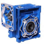
Structural characteristics of RV worm gear reducer:
1. High-quality aluminum alloy casting box, suitable for all-round universal installation and configuration;
2. Sufficient cooling ribs, so that the body has excellent thermal conductivity;
3. There are 10 chassis specifications from 025 to 150; the transmission power range is from 60W to 15KW;
4. The speed ratio range is large, and each single frame has 12 reduction ratios from 5:1 to 100:1;
5.Precision grinding and processing of hard tooth surface transmission worm, high efficiency and large output torque;
6. Low noise and stable operation, suitable for long-term continuous work in harsh environments;
7. Light weight and high mechanical strength;
8. The modular combination enables PCRW and DRW to expand the transmission ratio of the RW reducer to: i=5--32000.
Main materials of worm gear reducer:
1. RV reducer housing: aluminum alloy (frame: 025--090), cast iron (frame: 110--150);
2. Worm: 20Cr steel, carbon and nitriding treatment (maintain the tooth surface hardness HRC60 after fine grinding, the thickness of the hard layer>0.5mm);
3. Worm gear: specially formulated wear-resistant nickel bronze.
Paint for worm gear reducer:
1. Aluminum alloy:
1) After pill treatment, special anti-corrosion treatment (maintain the color of silver white alloy, and resist the corrosion of gasoline, etc.);
2) After phosphating treatment, spray RAL5010 blue baking paint;
2. Cast iron: sprayed with RAL5010 blue baking paint.
effectiveness
Efficiency is an important indicator of the reducer, which depends on the design and manufacture of the worm gear transmission pair and the friction condition. Since the reducer has different friction characteristics in the running state and in the stationary state, the efficiency of the reducer has dynamic efficiency and static efficiency correspondingly:
1. Dynamic efficiency ηd: the transmission efficiency of the reducer under operating conditions (dynamic friction);
2. Static efficiency ηS: the transmission efficiency of the reducer in the stopped state (static friction);
Since the static friction coefficient of the friction pair is greater than the dynamic friction coefficient, the dynamic efficiency of the reducer is greater than the static efficiency, that is, ηd>ηS.
RV reducer structure composition
1. The basic structure of RV reducer is mainly composed of transmission parts worm gear, shaft, bearing, box and accessories.
2. It can be divided into three basic structural parts: box body, worm gear, bearing and shaft combination.
3. The box is the base of all the accessories in the RV series reducer. It is an important accessory that supports the fixed shaft system components, ensures the correct relative position of the transmission accessories and supports the load acting on the RV reducer.
4. The main function of the worm gear is to transmit the motion and power between the two interleaved shafts, and the main function of the bearing and the shaft is to transmit power, operate and improve efficiency.
Generally speaking, the worm gear is a kind of transport mechanism. It can be used to transmit power in a lot of industrial fields. This transport mechanism is made up of two parts. It includes worm wheel and worm. The form of the worm is similar to the screw.
As a kind of the drive arrangement, the worm gear has its own unique features. The transport mechanism has the high transmission ratio. Meanwhile, it has the big axial force. In addition, its structure is more compact than the structure of bevel gear. In virtue of the above-mentioned features the drive mechanism is widely used in a lot of places.
In the following passage, we will talk about the advantages and the disadvantages of this drive mechanism in detail.
First, let us discuss the advantages of the worm gear. Compared with the bevel gear, the worm gear has the better meshing effectiveness and also it has the higher transmission ratio. What’s more, the worm gear is a kind of screw drive. The main transport form is the meshing drive. Therefore, the transmission is more stable and the vibration is smaller. This drive type is very applicable for the machines which work in stable working states. Last but not least, compared with other transport mechanics, the biggest advantage of the worm gear is its self-locking function. When the lead angle of the worm is smaller than the friction angle of the meshing gear, this transport mechanism will generate the reverse self-locking. At this time, the worm can drive the worm wheel,but it is impossible for the worm wheel to drive the worm. This self-locking function makes a great contribution to the safety of machines.
Second, let us analyze the disadvantages of the worm gear. As far as we know, everything has two sides just like a coin. There is no exception for this transport mechanism. The transmission efficiency of this transport mechanism is very poor. In addition, the abrasion is very serious in the transmission process. Why does this transport mechanism have these shortcomings? It is related to its drive form. The drive form of the Worm gear is the meshing gear transmission. The fast sliding speed results in the abrasion of tooth flanks. In order to reduce the abrasion of tooth flanks, the expensive materials are used by this transport mechanism. Therefore, the cost of the worm gear is increased. The price is more expensive.
A worm, in industrial parlance, is a shaft with a helical thread. It is commonly a part of a gear that meshes with a toothed wheel. Worm gears on the other hand, are those known as worm wheels. Sometime many people are confused with the terms worm, worm gear and worm drive, thinking that these three mean the same thing.
Worm gears are important especially when there is a need to reduce the gear size. It is the worm that has the capacity to make the gear rotate and not the other way around. With the shallow angle on the worm, the gear does not have the capacity to rotate it.
Types of worm gear
There are basically three different kinds of worm wheels: the non-throated; single throated; and double throated. Non-throated worm wheels are those that do not have throats in both the worms and the gear. Single throated categories are those whose gears are throated. Lastly, double throated ones are those with throated worms and gears.
Worm gear characteristics
There are notable traits of a worm wheel. First, it has the capacity to transfer and carry load with utmost accuracy. It is also best for large speed reductions. The efficiency of the worm gear, however, depends upon installation conditions, the worm’s lead angle, sliding speed, surface quality and lubricant selection.A process known as double enveloping makes worm gearing become more efficient. This technology enhances the existing features of the worm wheel. This leads to better accuracy and increased torque. What makes the technique so special is the fact that it may be used to produce better lubrication and design while loads are divided in each of the gear’s teeth.
Worm gear applications
Worm wheels make conveyor systems do its function. Conveyors are tools to transfer one material from one location to another. Aside from conveyor systems though, the worm wheel may also be used in high performance vehicles.
Worm gears are manufactured by way of milling its teeth through the help of a special machine. The entire output is completed according to the size needed by the particular industry. Whenever reducing friction is a concern, lubricants may be used. Examples are compounded mineral oils, extreme pressure mineral gear oils and synthetic worm gear oils. The lubricants will make the work of the machine faster and easier at the same time more efficient.
1 2