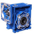
The reducer is a dynamic conveying mechanism. By adopting a gear reducer, the motor can achieve the required number of decelerations in rotation and obtain a larger torque. At present, the application range of the reducer has been widely used in the movement of transmission force and mechanism. From the construction of transport ships, automobiles, locomotives, heavy machinery, processing machinery and automated production equipment used in the machinery industry to ordinary household appliances, watches and the daily life of automobiles, its traces can be seen in almost all types of mechanical transmission systems . The cycloid reducer is one of the most common reduction machinery, often used in petrochemical, food industry, mechanical processing and other industries, with high transmission efficiency and long service life. Let’s explain its internal structure.
1. The output shaft can drive the required machinery and other devices through the output shaft. The output speed is decelerated
2. Fastening ring, for fixing
3. The gland is also used for fixing to prevent the internal objects from falling off
4. Input shaft, energy is usually provided by electric motor
5. Ventilation cap, for exhaust
6. For pin fixing
7. Spacer ring makes the flange or gear evenly stressed
8. Cylindrical sleeve sleeved outside the pin tooth pin and meshed with the cycloidal gear teeth
9. The main structure of cycloid wheel and reducer
10. Flange, transmission function
11. Fan blades are used to reduce the temperature of mechanical friction
12. Fastening ring for entering shaft for fixing and preventing loosening
13. Oil indicator, a device that shows the oil level
コメント