Introduction of helical gear reducer
Helical gear reducer is a novel reduction transmission device. Adopting the optimized and advanced design concept of modular combination system, it has the advantages of small size, light weight, large transmission torque, stable starting, fine transmission ratio classification, and can be connected at will and a variety of installation positions can be selected according to user requirements. The gears are made of high-quality high-strength alloy steel, and the surface is carburized and hardened, with strong load-bearing capacity and durability.
Classification of helical gear reducers
1. Involute helical gear reducer
The involute helical gear reducer has the characteristics of small size, light weight, high carrying capacity, high efficiency, long service life, convenient installation, wide range of motor power, and fine transmission ratio classification. It can be widely used in various industries that require deceleration equipment.
2. Helical gear worm gear reducer
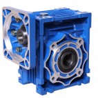
The helical gear worm gear reducer adopts the direct connection form of the motor, and the structure is a first-stage helical gear plus a first-stage worm gear drive. The output is shaft-mounted, with six basic installation forms. It can be rotated forward and backward. The helical gear adopts hard tooth surface, stable operation, large carrying capacity, and working environment temperature -10℃~40℃. Compared with similar products, this product has the characteristics of large speed range, compact structure and convenient installation. It can be widely used in the deceleration mechanism of various mechanical equipment such as metallurgy, mining, lifting, light industry, chemical industry, transportation, construction and so on.
3. Helical gear worm gear reducer
The helical gear worm gear reducer adopts the direct connection form of the motor, and the structure is a first-stage helical gear plus a first-stage worm gear drive. The output is shaft-mounted, with six basic installation forms. It can be rotated forward and backward. The helical gear adopts hard tooth surface, stable operation, large carrying capacity, and working environment temperature -10℃~40℃. Compared with similar products, this product has the characteristics of large speed range, compact structure and convenient installation. It can be widely used in the deceleration mechanism of various mechanical equipment such as metallurgy, mining, lifting, light industry, chemical industry, transportation, construction and so on.
Helical gear reducer is a novel reduction transmission device. Adopting the optimized and advanced design concept of modular combination system, it has the advantages of small size, light weight, large transmission torque, stable starting, fine transmission ratio classification, and can be connected at will and a variety of installation positions can be selected according to user requirements. The gears are made of high-quality high-strength alloy steel, and the surface is carburized and hardened, with strong load-bearing capacity and durability.
Classification of helical gear reducers
1. Involute helical gear reducer
The involute helical gear reducer has the characteristics of small size, light weight, high carrying capacity, high efficiency, long service life, convenient installation, wide range of motor power, and fine transmission ratio classification. It can be widely used in various industries that require deceleration equipment.
2. Helical gear worm gear reducer
The helical gear worm gear reducer adopts the direct connection form of the motor, and the structure is a first-stage helical gear plus a first-stage worm gear drive. The output is shaft-mounted, with six basic installation forms. It can be rotated forward and backward. The helical gear adopts hard tooth surface, stable operation, large carrying capacity, and working environment temperature -10℃~40℃. Compared with similar products, this product has the characteristics of large speed range, compact structure and convenient installation. It can be widely used in the deceleration mechanism of various mechanical equipment such as metallurgy, mining, lifting, light industry, chemical industry, transportation, construction and so on.
3. Helical gear worm gear reducer
The helical gear worm gear reducer adopts the direct connection form of the motor, and the structure is a first-stage helical gear plus a first-stage worm gear drive. The output is shaft-mounted, with six basic installation forms. It can be rotated forward and backward. The helical gear adopts hard tooth surface, stable operation, large carrying capacity, and working environment temperature -10℃~40℃. Compared with similar products, this product has the characteristics of large speed range, compact structure and convenient installation. It can be widely used in the deceleration mechanism of various mechanical equipment such as metallurgy, mining, lifting, light industry, chemical industry, transportation, construction and so on.
Problems with the motor itself
1. Open circuit of motor winding
When one of the windings of the motor is broken, or one of the parallel branches is broken, it will cause the three-phase current to be unbalanced and the motor will overheat.
2. Short circuit of motor winding
When the motor winding has a short-circuit fault, the short-circuit current is much larger than the normal working current, which increases the copper loss of the winding, and causes the winding to overheat and even burn.
3. Wrong connection of motor star angle
When the delta connection motor is wrongly connected in a star shape, the motor is still running with full load, and the current flowing through the stator winding will exceed the rated current, which may even cause the motor to stop by itself. If the stoppage time is a little longer and the power supply is not cut off, the winding is not only serious Overheating, it will burn. When a star-connected motor is wrongly connected to form a triangle, or a motor with several coil groups stringed into a branch is connected to two branches in parallel, the winding and the iron core will be overheated, and the winding will be burnt in severe cases.
4. Wrong connection of motor coil
When a coil, coil group or one-phase winding is connected reversely, it will cause serious imbalance of the three-phase current and overheat the winding.
5. Mechanical failure of the motor
When the motor shaft is bent, the assembly is not good, the bearing is defective, etc., the motor current will increase, copper loss and mechanical friction loss will increase, and the motor will overheat.
Ventilation and heat dissipation problems
1. The ambient temperature is too high, making the inlet air temperature high.
2. There is debris blocking the air inlet, which makes the air inlet not smooth, resulting in a small amount of air inlet.
3. Excessive dust inside the motor affects heat dissipation.
4. The fan is damaged or installed reversely, resulting in no wind or small air volume.
5. There is no wind shield or no wind baffle in the motor end cover, resulting in the motor without a certain air path. 5 The problem of repairing the motor The starting current of the repaired motor reaches more than 66%, and the frequent operation of the motor will also cause high current and cause the motor to overheat.
6 Series resistance problem The winding motor does not match the series resistor, etc. At the same time, the frequent operation of the motor will also cause high current and cause the motor to overheat.
7 Motor vibration problems. Excessive motor vibration may also cause high motor current. Reasons and solutions:
1. Rotor unbalance-leveling balance
2. Unbalanced pulley or bent shaft extension-check and correct
3. The axis of the motor and the load are not aligned-check and adjust the axis of the unit
4. The motor is not properly installed-check the installation and the foot screws
5. The load is suddenly too heavy-reduce the load
In fact, the deafening noise of the hard-tooth surface reducer is simply because of four reasons. The four problems are solved at the source and the noise is automatically eliminated.
The first reason is that the gears of the hard-tooth surface reducer are damaged, resulting in a large amount of wear and vibration between the gears, so that the hard-tooth surface reducer has great noise during operation. Not only that, but also greatly affects the hard surface. The normal operation of the gear reducer.
The second reason is that the ground on which the hard-tooth surface reducer is installed is not stable, which causes the hard-tooth surface reducer to shake violently due to the unstable position during operation, resulting in noise.
The third reason is that the internal system of the hard-tooth surface reducer is faulty. Generally, the internal parts of the hard-tooth surface reducer are missing or damaged, which causes huge noise.
The fourth reason is the improper operation and use of the hard-tooth surface reducer, resulting in excessive load or improper speed, which will generate great noise.
When the hard-tooth surface reducer has a lot of noise, it is nothing more than these four reasons. As long as these four problems are completely solved, the hard-tooth surface reducer will naturally eliminate the noise.
Geared motors are widely used in various industrial production lines, conveying machinery, food machinery, medical machinery, printing machinery, textile machinery, office equipment, instrumentation, advertising, amusement facilities and other industries. Sometimes the geared motor is in use. There will be heat generation, so how much do you know why the geared motor heats up?
1. The room temperature is too high
2. Poor heat dissipation
3. Overload
4. Rotor sweep bore
5. Frequent start and stop or frequent forward and reverse rotation
6, the motor is damp
7. The fan is broken or the air inlet and outlet are blocked
8. Bearing lack of oil
9. Overvoltage, undervoltage or unbalanced voltage
10. The load moment of inertia is too large and the starting time is too long
11. Short circuit between turns
12. The internal wiring of the new motor is incorrect
13. The star-delta wiring is wrong
14. Star-delta or self-dual step-down start-up load restart time is long or abnormal conversion due to failure
15. The machine is stuck in a stall
16. Broken bar of squirrel cage asynchronous motor rotor
17. The rotor winding of the wound asynchronous motor is broken or the resistance is unbalanced
18, lack of phase
19.The harmonics of the power supply are too large, such as large rectifier equipment, high-frequency equipment, etc. nearby
Why does the planetary deceleration opportunity appear broken axis imagination? First of all, the biggest possible problem with the broken shaft is the quality of the planetary reducer. Of course, this is what we can think of in ordinary times, and the main reason is the reason in the usual use process. For example, what should we pay attention to when using planetary reducer to accelerate and decelerate, and what good methods are there.
1. Some applications must strictly abide by this criterion. This is not only to protect the reducer, but also to prevent the output shaft of the planetary reducer from being twisted. This is mainly because if there is a problem with the installation of the equipment, the output shaft of the reducer and its load are jammed. At this time, the overload capacity of the drive motor will continue to increase its output, which may cause the output bearing of the reducer to be affected. The force exceeds 2 times the rated output torque and twists the output shaft of the reducer.
2. In the process of acceleration and deceleration, if the momentary torque applied to the output shaft of the planetary reducer exceeds twice its rated output torque, and the acceleration and deceleration are too frequent, the reducer will eventually be broken. axis.
3. The wrong type selection results in insufficient output of the equipped reducer. Some users mistakenly think that as long as the rated output torque of the selected planetary reducer meets the working requirements, it is not true. First, the rated output torque of the equipped motor is multiplied by the reduction ratio, and the value obtained is in principle less than The product catalog provides the similar rated output torque of the reducer. Second, the overload capacity of the drive motor and the actual maximum operating torque required must be considered at the same time.
How to effectively inspect and maintain the reducer. Different lubricating oils are not allowed to be mixed with each other. The positions of the oil level plug, the oil drain plug and the breather are determined by the installation position. Their relative positions can be determined with reference to the installation position diagram of the reducer.
1. For the reducer with oil level plug
Check the oil level, whether it is qualified; install the oil level plug.
2. Oil replacement
After cooling, the viscosity of the oil increases and it is difficult to drain the oil. The reducer should change the oil at the operating temperature. Cut off the power to prevent electric shock! Wait for the reducer to cool down and there is no danger of burning!
Three, matters needing attention
Inject new oil of the same brand; the amount of oil should be consistent with the installation position; check the oil level at the oil level plug; tighten the oil level plug and breather; the reducer should still be warm when changing the oil; the oil plug should be drained Place an oil pan below; open the oil level plug, breather and oil drain plug; drain all the oil; install the oil drain plug.
Fourth, check the oil level
Cut off the power to prevent electric shock! Wait for the reducer to cool down; remove the oil level plug to check if the oil is full; install the oil level plug.
Five, oil inspection
Cut off the power to prevent electric shock! Wait for the reducer to cool down; open the oil drain plug and take an oil sample; check the viscosity index of the oil; if the oil is obviously muddy, it is recommended to replace it as soon as possible.
The working principle of the precision planetary reducer is as follows:
1) The ring gear is fixed, the sun gear is active, and the planet carrier is passive.
This combination is a reduced speed transmission, usually the transmission ratio is generally 2.5-5, and the steering is the same.
2) The ring gear is fixed, the planet carrier is active, and the sun gear is passive.
This kind of combination is a speed-up transmission, the transmission ratio is generally 0.2 to 0.4, and the steering is the same.
3) The sun gear is fixed, the ring gear is active, and the planet carrier is passive.
This combination is a reduced-speed transmission, the transmission ratio is generally 1.25 to 1.67, and the steering is the same.
4) The sun gear is fixed, the planet carrier is active, and the ring gear is passive.
This kind of combination is a speed-up transmission, the transmission ratio is generally 0.6 to 0.8, and the steering is the same.
5) The planet carrier is fixed, the sun gear is active, and the ring gear is passive.
This combination is a reduced speed transmission, the transmission ratio is generally 1.5 to 4, and the direction of rotation is reversed.
6) The planet carrier is fixed, the ring gear is active, and the sun gear is passive.
This kind of combination is a speed-up transmission, the transmission ratio is generally 0.25 ~ 0.67, and the direction of rotation is opposite.
7) Combining any two of the three elements into one unit:
When the planet carrier and the ring gear of the precision planetary reducer are integrated as the active part, the sun gear is the passive part or the sun gear and the planet carrier are integrated as the active part, and the ring gear is the passive part. There is no relative movement between the planetary gears, they operate as a whole, the transmission ratio is 1, and the rotation is the same.
Geared motors are also called geared motors, and they are more and more widely used in our daily lives. Excessive temperature rise of the geared motor is also a common heat. During operation, there are many reasons for the excessive temperature rise of the geared motor. Only by finding the right cause can the geared motor failure be completely and effectively eliminated.
1. The stator winding is short-circuited or grounded between turns or between phases, which will increase the current, increase the regulation loss and overheat. If the fault is not serious, just re-pack the insulation, and if it is serious, replace the winding.
2. The one-phase winding of the stator is broken or a branch of the parallel winding is broken, causing the three-phase current to be unbalanced and the windings are overheated.
3. Broken bars of the cage rotor or loose joints of the wound rotor coils cause excessive current in the maintenance network and heat generation. The copper bar rotor can be welded or replaced, and the cast aluminum rotor should be replaced.
4. The bearing is damaged or worn too much, causing the stator and rotor to rub against each other. Check whether the bearing is loose and whether the stator and rotor are poorly assembled.
5. If the load is too large, the load should be reduced or a high-power motor should be used.
6. If the belted working machine is faulty and causes overload, check the belted machine and eliminate the fault.
7. To start too frequently, the number of starts should be reduced.
8. The operating environment temperature is too high (over 40°C), which makes the three-phase inlet air too hot and difficult to dissipate heat. Cooling measures should be taken.
9. There is too much dust and oil pollution inside and outside the motor, which affects heat dissipation, so dust and oil pollution should be eliminated.
10. The air duct of the motor is blocked, the ventilation is not smooth, and the air intake is reduced. The debris and dirt at the air duct should be eliminated.
11. If the fan in the motor is damaged, installed upside down or not installed, it should be installed correctly, and the damaged fan should be repaired or replaced.
12. When the voltage exceeds the rated voltage of the motor by more than 10%, or is lower than the rated voltage of the motor by more than 5%, the motor will easily heat up under the rated load, and the temperature rise will increase. The Dalan motor manufacturer recommends that you check and adjust the voltage.
13. The phase-to-phase imbalance of the three-phase power supply voltage exceeds 5%, which causes the three-phase current imbalance, which causes the motor to generate additional heat, and the voltage should be adjusted.
14. The one-phase fuse is open or the power switch is in poor contact, which causes the lack of phase operation and overheating. The damaged components should be repaired or replaced.
15. The three-phase motor winding wiring is wrong. If the star is connected to a delta by mistake, or the delta is connected to a star by mistake, running under the rated load will cause the motor to overheat and should be checked and corrected.
The reducer is a dynamic conveying mechanism. By adopting a gear reducer, the motor can achieve the required number of decelerations in rotation and obtain a larger torque. At present, the application range of the reducer has been widely used in the movement of transmission force and mechanism. From the construction of transport ships, automobiles, locomotives, heavy machinery, processing machinery and automated production equipment used in the machinery industry to ordinary household appliances, watches and the daily life of automobiles, its traces can be seen in almost all types of mechanical transmission systems . The cycloid reducer is one of the most common reduction machinery, often used in petrochemical, food industry, mechanical processing and other industries, with high transmission efficiency and long service life. Let’s explain its internal structure.
1. The output shaft can drive the required machinery and other devices through the output shaft. The output speed is decelerated
2. Fastening ring, for fixing
3. The gland is also used for fixing to prevent the internal objects from falling off
4. Input shaft, energy is usually provided by electric motor
5. Ventilation cap, for exhaust
6. For pin fixing
7. Spacer ring makes the flange or gear evenly stressed
8. Cylindrical sleeve sleeved outside the pin tooth pin and meshed with the cycloidal gear teeth
9. The main structure of cycloid wheel and reducer
10. Flange, transmission function
11. Fan blades are used to reduce the temperature of mechanical friction
12. Fastening ring for entering shaft for fixing and preventing loosening
13. Oil indicator, a device that shows the oil level
The competition of reducer products in automation equipment is becoming increasingly fierce. With the continuous development of society, precision planetary reducers are more and more widely used, and noise is used as a performance indicator of the quality of servo planetary reducers. For the noise source of the servo planetary reducer, the reasons must be analyzed and studied from the design, maintenance and installation of the reducer.
(1) The influence of the parameters and structure design of the core part gear of the servo planetary reducer on noise; a pair of gears are in transmission. The higher their overlap, the lower the noise generated. Of course, the smaller the coincidence degree, the higher the noise. It means that the number of gear teeth participating in meshing at the same time increases, which is of great significance for improving the smoothness of gear transmission, reducing noise and improving load-carrying capacity.
(2) The gear accuracy grade is an important indicator of the noise level. For the standard series of servo planetary reducers, the gear manufacturing accuracy determines its noise value. The higher the gear precision, the denser the contact spots on the meshing tooth surface, the contact spots on the entire tooth surface, the lower the noise. On the contrary, the lower the gear accuracy, the smaller the contact scars on the meshing tooth surface, and the gear cannot be completely meshed in its contact width, the operation will be unstable, and even cause impact, which will increase the noise value.
(3) Impact and noise caused by pitting on the tooth surface; after the transmission gear is loaded and operated for a period of time, small pieces of metal often fall off near the pitch line of the tooth surface, forming pitting corrosion. Because the hard tooth surface gear has a large load-bearing capacity and volume The advantages of small size, light weight, and good transmission quality are widely used, although hard-faced gears are not prone to pitting. But once pitting occurs, it is not easy to run-in. The pitting corrosion of the tooth surface will continue to expand rapidly as the working time increases. Developed into extended pitting. The tooth shapes are broken each other, and the working noise and impact are increased. The metal chips dropped by the impact accelerate the wear of the tooth surface, which makes the gear transmission unstable and produces noise.
(4) Gear machining errors are easy to cause noise; the errors generated during gear machining lead to noise mainly due to accumulated errors in tooth pitch and tooth profile errors. The cumulative error of the tooth pitch is due to the non-coincidence of the rotation axis of the tooth blank with the rotation axis of the gear when the gear is working, resulting in uneven gear tooth thickness. Tooth profile error is mainly caused by errors in the manufacturing, sharpening and installation of the hob, which cause the tooth surface to be edged, the tooth profile is asymmetry, undercut and subsequent processing are not fully corrected, which makes the gear transmission unstable. The phenomenon of pulsation, undercutting and tooth punching occurs and then noise is generated.
(5) The elastic deformation of the tooth surface of the heavy-duty gear drive causes noise; The heavy-duty gear, especially the hard-tooth gear, has a large elastic deformation and extremely poor running-in performance. The impact of the gears caused by the load deformation produces noises. .
In short, the noise source of the servo planetary reducer is related to the design, manufacturing, assembly accuracy and maintenance of the whole machine, and strive to improve the smoothness of the transmission and reduce the noise.
At present, my country’s industrial energy consumption accounts for about 70% of the total energy consumption, of which the motor energy consumption accounts for about 60% to 70% of the industrial energy consumption. In addition to the non-industrial motor energy consumption, the actual energy consumption of the motor accounts for about 50% of the total energy consumption. Above, the current application of high-efficiency energy-saving motors is low. According to a sample survey of 198 motors from key domestic enterprises conducted by the National Center for Quality Supervision and Inspection of Small and Medium-sized Motors, only 8% of them have high-efficiency and energy-saving motors that reach level 2 or above, which is a huge waste of social resources.
Features of high-efficiency motors
1. It saves energy and reduces long-term operating costs. It is very suitable for textiles, fans, water pumps, and compressors. It can recover the purchase cost of the motor by saving electricity in one year;
2. Direct start or use frequency converter to adjust the speed, the asynchronous motor can be fully replaced;
3. The rare earth permanent magnet high-efficiency energy-saving motor itself can save more than 15℅ electric energy compared with ordinary motors;
4. The power factor of the motor is close to 1, which improves the quality factor of the power grid without adding a power factor compensator;
5. The motor current is small, which saves the transmission and distribution capacity and prolongs the overall operating life of the system;
6. Power saving budget: Taking 55 kilowatt motors as an example, high-efficiency motors save 15% of electricity compared to ordinary motors. The electricity bill is calculated at 0.5 yuan per kilowatt-hour. The cost of replacing the motor can be recovered by saving electricity within one year of using energy-saving motors.
Future development of high-efficiency motors
Favorable policies drive the industry to advance to the high-end. The prospects for my country’s motor market are expected. For a long time, due to technical limitations, my country’s motor manufacturers have focused on the low-end market, which has led to more and more crowded domestic markets, but there will be progress if there is competition. , Accompanied by domestic manufacturers "fighting together", my country’s motor market has gradually moved towards the high-end field. In the context of global reduction of energy consumption, high-efficiency and energy-saving motors have become the consensus of the development of the global motor industry.
In the future, my country will gradually increase its efforts to promote high-efficiency motors, eliminate low-efficiency motors in use, develop high-efficiency motor remanufacturing, and comprehensively promote the development of motor products in the direction of high efficiency, high reliability, light weight, and miniaturization, and further promote energy conservation. The length of the motor’s life has a very large relationship with the temperature rise, improving the efficiency of the motor and reducing the temperature rise can effectively extend the service life of the motor. The lightweight and miniaturization of the motor will help save materials and space. Therefore, the development of high-efficiency and ultra-efficient small and medium-sized motors, special motors for speed regulation, energy-saving control products for motor systems, and research on green energy-saving technologies for motors and systems have become a new development trend in the motor industry.
What are the characteristics and specifications of three-phase asynchronous motors? Generally speaking, small asynchronous motors refer to induction motors. This kind of motor not only uses auxiliary coils and capacitors when it is started, but also when it is running. Although the starting torque is not very large, it has a simple structure, high reliability, high efficiency, and continuous operation.
Asynchronous motor characteristics:
1. Generally speaking, small asynchronous motors refer to induction motors. This kind of motor not only uses auxiliary coils and capacitors when it is started, but also when it is running. Although the starting torque is not very large, it has a simple structure, high reliability and high efficiency.
2. It can run continuously.
3. With the size of the load, the rated speed of the motor will also change.
4. Used in applications that do not require speed braking.
5. Insulation grade E is used, while type A is used for UL type motors.
6. There are two types of induction-running single-phase asynchronous motors and three-phase asynchronous motors.
7. The single-phase motor is an induction-running asynchronous motor with high efficiency and low noise.
8. The power supply of single-phase motor includes A (110V 60Hz), B (22V 60Hz), C (100V 50/60Hz), D (200V 50/60Hz), E (115V 60Hz), X (200-240V50Hz), etc.
9. When a single-phase asynchronous motor is running, it produces a torque opposite to the direction of rotation, so it is impossible to change the direction in a short time. The direction of rotation of the motor should be changed after the motor has completely stopped.
10. In the case of three-phase motors, asynchronous motors with U (200V 50/60Hz), T (220V 50/60Hz), S (380-440V 50/60Hz) power supplies are used.
Specification of asynchronous motor:
Insulation resistance
After running the motor at normal temperature and humidity, use a DC 500V insulation resistance meter to measure the motor. The insulation resistance between the metal resistance and the motor shell exceeds 100M?
Insulation internal pressure:
Under normal temperature and humidity, after running the motor, the voltage between the metal winding of the motor and the motor box
With the further development of China’s machinery industry, more and more users are using reducers. The reducer uses a gear reducer to reduce the speed of the motor to the required speed. At the same time, greater torque will be achieved. In all current power transmission mechanisms, reducers have a wide range of applications. It can be seen in almost all transmission systems of various machines. It can be used for transportation such as ships, automobiles, motorcycles, etc. It can also be used for machinery in heavy construction equipment, industrial processing machinery and automated production equipment.
So in the normal work of the reducer, will the temperature affect the normal operation of the reducer?
1. The limit operating temperature refers to the temperature of the hot spot during operation of the reducer during the expected life of the design. If the operating temperature exceeds the limit operating temperature for a long time, it will accelerate the aging of the insulating material, thereby greatly shortening the service life of the reducer. Therefore, during the operation of the reducer, temperature is one of the main factors affecting the service life of the reducer.
2. Temperature rise refers to the temperature difference between the reducer and the environment, which is generally caused by the heat of the reducer. The temperature rise is an important indicator of the reducer during operation, which can clearly know the degree of heat of the reducer. During work, if the temperature of the reducer suddenly rises, it means that the reducer is malfunctioning, the vent is blocked, or the reducer is overloaded.
3. During the operation of the reducer, its iron core is located in the alternating magnetic field, which will produce iron loss. The winding will produce copper loss after energization, and other losses will be mixed, which will lead to the temperature of the reducer. Elevated. The reducer itself has a heat dissipation function. When the heat and heat dissipation are equal, it will be in a balanced state. If the temperature suddenly rises at this time to break this balance, the temperature will continue to rise, thereby affecting the normal operation of the reducer.
The reducer will be affected by the temperature when it is working, so it is necessary to keep a stable temperature during the working process, so as to extend the service life of the reducer.
The reducer sounds like it is only used in industry and machinery manufacturing, but it is actually used in all aspects of our lives.
The reducer is divided into high-power reducer and low-power reducer (micro reducer), which are used in different fields.
1. Electronic products and equipment
Mobile phones, digital cameras, handheld fans, balance cars, drones, electronic locks, electric toothbrushes, intelligent interactive robots, electric dolls, printers, photocopiers, etc.
2. Smart home, smart home appliances
Air conditioners, washing machines, sweepers, vacuum cleaners, smart toilet cleaning pumps, smart sensor trash cans, electric curtains, sun shades, blinds, electric drying racks, electric projectors, etc.
3.automobile transmission gear box
Car window shutters, car sunroofs, wipers, headlight regulators, tailgate motors, electric push rods, EPB, rearview mirror regulators, automatic steering wheel motors, stepper motors, car protection headrest motors, car antenna motors, etc. Wait.
4.smart medical motor
Insulin pump gearbox motor, smart massage shoe motor, massage chair motor, minimally invasive linear stapler, smart infusion controller, self-setting knife motor, dragon claw massager motor, etc.
5. intelligent equipment
Telecom base station antenna adjustment motors, automatic packaging machine gearboxes, ATM machine motors, automatic vending machines, automatic ticket dispensers, robot transmissions, unmanned aerial vehicles, security rotating cameras, etc.
Cycloidal pin gear reducer is a novel transmission mechanism that adopts K-H-V planetary transmission principle with little tooth difference and meshing of cycloidal pin teeth. It is widely used in driving and decelerating devices in the fields of textile printing and dyeing, light industry and food, metallurgy and mining, petrochemical industry, lifting and transportation and construction machinery.
At present, cycloidal reducers are manufactured in the world, and Japan has done more and better. The basic structure of the cycloid reducer includes the input eccentric roller bearing, the planetary cycloid gear plate, the body and the outer needle teeth. The characteristic of the cycloid reducer is that it is obvious that the reduction ratio is high and the range is large, and the reduction ratio of single-stage transmission is 50-200. The transmission efficiency is higher than that of a worm gear reducer. With different reduction ratios, the efficiency of a single-stage transmission is 60-70%. Another characteristic of him is that due to the frictional movement, the torsional rigidity is low.
The disadvantage of this type of machine is that because it is eccentric and frictional, the transmission components are easily worn out, the working life is short, and the machine is prone to heat generation and temperature rise, so the allowable input speed is not high, and it is also below 2,000rpm.
Worm gear reducer is composed of input worm and output worm. It is characterized by high transmission torque, high reduction ratio and large range. The reduction ratio of single-stage transmission is 5-100; transmission mechanism is not coaxial input and output, application It is not easy, and the transmission efficiency is the lowest, not exceeding 60%.
Due to the relative sliding friction transmission, the torsional rigidity of the worm gear reducer is slightly lower, and the transmission components are easily worn out, the working life is short, and the reducer is prone to temperature rise, so the allowable input speed is not high (2,000rpm), which is limited The use of worm gears is described.
1. Water leakage of tubular oil cooler:
Block the two ends of the leaking tandem pipe; when the tandem pipe is enlarged, increase the seepage level again and press down to test the seal.
2. Oil leakage problem:
If there is oil leakage at the connection between the oil inlet pipe and the reducer housing, re-block, clean the seepage area and weld; if there is oil leakage at the housing connection, re-tighten and loosen the bolts.
3. The problem of insufficient oil pressure of the oil pump
After the original two-blade dual-flow oil pump of the main reducer oil station was operated for two months, the oil pressure dropped and fluctuated severely, and the final oil pressure was below the lower limit; due to the chain system control, the mill could not start: select and update 2 domestic oil pumps, and reconfigure Valves and pipes.
4. Oil pump motor overload:
Due to the low oil temperature and high oil viscosity, the resistance increases. By increasing the oil temperature, the problem can be eliminated.
5. Bolt loosening problem (the main reducer connecting ring and the shell bolts are loose, even 9 bolts are broken, and the radial limit pin is loosened or moved):
Remove the broken bolts, replace all high-strength connecting bolts and tighten them to stabilize the limit pin. It is recommended to tighten the connecting bolts (including anchor bolts) in various parts in time after the equipment is installed and operated for one month to prevent the body from loosening.
6. The original design of the reducer only has a temperature measurement point installed on the oil return pipe, and the temperature should not exceed 56 degrees, otherwise it will automatically alarm and stop, but it cannot truly reflect the actual situation of the bearing. Internal temperature conditions. It is recommended to consider the temperature measurement points of key parts in the design, grasp and understand the actual situation of each part, and solve and deal with problems in time.
There are several reasons for the overheating of the motor in terms of power supply:
Power supply voltage is too high
When the power supply voltage is too high, the motor back electromotive force, magnetic flux and magnetic flux density will increase accordingly. Since the size of the iron loss is proportional to the square of the magnetic flux density, the iron loss increases, causing the core to overheat. The increase in magnetic flux also causes the component of the excitation current to increase sharply, resulting in increased copper loss in the stator winding and overheating of the winding. Therefore, when the power supply voltage exceeds the rated voltage of the motor, the motor will overheat.
When the power supply voltage is too low, if the electromagnetic torque of the motor remains unchanged, the magnetic flux will decrease, the rotor current will increase correspondingly, and the load power component of the stator current will increase accordingly, causing the copper loss of the winding to increase. Cause the stator and rotor windings to overheat.
Asymmetric power supply voltage
When one phase of the power cord is broken, the fuse is blown in one phase, or the corner of the knife starting device is burned and one phase is blocked, it will cause the three-phase motor to go single-phase, causing the running two-phase winding to overheat through high current and even burn. Therefore, fuse protection is generally not suitable for three-phase motors.
Three-phase power unbalance
When the three-phase power supply is unbalanced, the three-phase current of the motor will be unbalanced, causing the winding to overheat. It can be seen from the above that when the motor is overheated, the power source should be considered first (soft start, frequency converter, servo drive can also be regarded as power source).
There are several reasons for the motor overheating in terms of load:
1. Motor overload operation When the equipment is not matched and the load power of the motor is greater than the rated power of the motor, the motor will be overloaded for a long time (ie a small horse-drawn cart), which will cause the motor to overheat. When repairing an overheated motor, you should first find out whether the load power is consistent with the motor power to prevent blind disassembly.
2. The dragged mechanical load is not working properly. Although the equipment is matched, the dragged mechanical load is not working properly. During operation, the load is large and sometimes small, and the motor is overloaded and heats up.
3. The dragging machinery is faulty. When the dragging machinery is faulty, rotating inflexibly or being stuck, it will overload the motor and cause the motor winding to overheat. Therefore, when the motor is overheated, the load factor cannot be ignored.
Turbine reducer is a kind of transmission equipment, because the wear and temperature caused by continuous operation will affect the service life and performance of the turbine reducer. In addition, if the turbine reducer does not take any maintenance measures in the long-term working condition, it will also cause the oil leakage of the reducer. The vibration of the reducer and the wear of the bearings, gears, and turbines of the various components will also cause oil leakage. Determine whether to replace worm gears, gears, bearings and other parts according to the degree of wear.
Because the turbine reducer case is sealed, and the turbine, gears, bearings, reduction box, etc. are all made of hard steel, the heat dissipation performance is not high. . Therefore, during the operation of the worm gear reducer, the temperature in the reduction box will become higher and higher, which will cause the differences in the fit of the components due to the different coefficients of thermal expansion. The oil temperature continues to rise, resulting in poor oil quality, which affects the lubrication performance of gears, turbines, and bearings, and ultimately leads to oil leakage and other failures of the reducer. The degree of wear of turbines and gears is related to the materials of their own construction, as well as factors such as material collocation and lubricant quantity.
The three major issues that cannot be ignored when using a worm gear reducer are as follows:
1. It is strictly forbidden to knock:
When installing couplings, pulleys, sprocket and other coupling elements on the output shaft of the reducer, direct hammering is not allowed for operation. Because the output shaft structure of the reducer cannot withstand axial hammering, the screw hole can be screwed into the shaft end to press into the coupling.
2. Be sure to install a breather cap (ie exhaust screw plug):
When using the reducer, be sure to replace the plug on the top of the reducer with an exhaust screw plug. The function of replacing the exhaust screw plug is to ensure that the reducer is working to remove the gas generated in the inner body of the reducer. Otherwise, when the reducer is working for a long time, the gas in the reducer will adhere to the longer the working time and increase, and the temperature rise will cause the oil seal of the reducer to swell and damage, causing the reducer to leak oil.
3. Replacement of lubricating oil:
The user determines the amount of lubricating oil to be injected according to the size of the reducer. There are specific regulations for this, and the specific operation should follow the reducer’s manual. If the reducer is placed in a working environment with harsh environment, high temperature, and large dust, please be sure to check or replace the lubricant every 12 days.
Gear reducer is the most widely used one among the reducers, which are very common in metallurgy, textile, steel, automation machinery and other industries. In the use of gear reducers, it is necessary to pay attention to many places to fully display the functions of the gear reducer. Gear reducers are generally used for low-speed and high-torque transmission equipment. There are also several common reducers for motors. To achieve the ideal deceleration effect for gears of the same principle, the ratio of the number of teeth of the large and small gears is the transmission ratio. With the continuous development of the reducer industry, more and more industries have used reducers. The following briefly introduces several industries where gear reducers are applied:
1. Application of gear reducer on stage equipment
The drive equipment must not only meet the requirements of safety, reliability and low noise, but also be installed in an appropriate location!
2. Application of gear reducer in lifting industry
Choosing the right drive equipment that can optimize the internal process plays a decisive role in ensuring the economy and safety of the lifting system.
3. Application of gear reducer in steel industry
The hardened gear reducer is strong and reliable in the production line of the steel plant, and the maintenance interval is long.
4. Application of gear reducer in airport equipment
The driving system used in airport equipment uses a two-stage helical bevel gear reducer to replace the traditional worm gear reducer, which highlights the technological change. Since the maintenance interval of the reducer is extended, especially the more wear-resistant parts are used, the maintenance cost of the drive system is lower, and the initial investment cost is effectively reduced.
6. Application of gear reducer in water treatment
Vertical installation geared motor for aerator, double-layer rain cover, IP66 protection grade, retest three-lip seal ring, TF motor thermal protection. If the reducer is outdoors, in humid areas or tropical areas, it is necessary to consider the use of special seals and anti-corrosion measures.
The reducer is a power transmission device. It uses a gear reducer to reduce the speed of the motor to the required speed. At the same time, greater torque will be achieved. In all current power transmission mechanisms, reducers have a wide range of applications. It can be seen in almost all transmission systems of various machines. It can be used for transportation such as ships, automobiles, motorcycles, etc. It can also be used for machinery in heavy construction equipment, industrial processing machinery and automated production equipment. In addition, it can be seen in our daily lives. For example, it can be used in household appliances, watches, etc. Thus, we can see that it has a wide range of applications, from large transmission tasks to small loads. As for its use in industry, the reducer can reduce the speed and increase the torque function. Therefore, it can be widely used in speed and torque conversion devices.
Because the reducer has such a wide range of uses, the acceptance of the machine is very important.
1. All parts of the machine body are complete, intact and firm.
2. The bolt connections must be complete, complete, firm and reliable.
3. The bolts must not be bent, the thread wear must not exceed half of the working height, and the connection must not exceed one week.
4. The nut must be tightened, and the screw thread of the bolt should expose the nut with 1~mm3 pitch. No extra washers should be added under the nut to reduce the exposed length of the bolt.
5. The transmission gears at all levels have no defects such as pitting, deformation, and tooth surface peeling. The meshing position is moderate, the meshing area is not less than 60%, and the meshing length is not less than 75%.
6. The bearing rollers and raceways have no pitting, pitting and spalling, the cage has no deformation and loosening, and the clearance in all directions meets the requirements.
7. The housing of the reduction gearbox must not be cracked or deformed, and the joint surface must be tightly matched without oil leakage.
8. The oil in the gearbox is clean and the amount of oil is appropriate.
9. The overall appearance is clean and rust-removed, the paint is evenly painted, and there is no overflow, bubbling and peeling.
10. During the no-load test run, the following requirements should be met:
(1) Smooth transmission, no abnormal sound, and no abnormal rise in temperature.
(2) Good sealing and no oil leakage.
(3) There is no looseness of fasteners and connecting parts.
1 2